1505300-13 Airport Design in terms of minimizing excess pavement. Runway Taxiway Designing of Aerodrome Design Manuals.
2
Dimensions such as runway and taxiway widths runway to taxiway separation standards and obstacle clearance items.

. Taxiway Edge Marking Taxiway edge markings are used to delineate the edge of the taxiway. Airport Runway and Taxiway Design CAD Template DWG. Use the FAA Taxiway Fillet Design Tool to design the centerline radius and fillets for turns comprising all deltas between 5 and 175 degrees including centerline lights and optionally edge lights.
The term OMGWS is an important input parameter when determining runway and taxiway widths. Under this methodology safety margins are provided in the physical design of airport facilities. RUNWAY DESIGN Standards RUNWAY DESIGN Runway Design Standards Guidance provided in Chapter 3 of FAA AC 1505300-13A Also in ICAO Annex 14 Aerodrome Design and Operation Used to determine physical dimensions for.
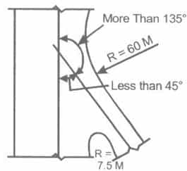
Bypass taxiway Entrance Taxiway. Of the taxiway at the hold short line the runway guard lights are meant to draw attention to the hold short line - the area where a taxiway meets the runway. For airport serving large subsonic jet transports minimum value of redius of curvature is 120 m whatever be the speed.
If you place any road in the vicinity of the runwaytaxiway it will fix the issue. Taxiway design Turning Radius where R is the radius of curve in m V is ther speed in kmph and f is the coefficint of friction between the tyre and pavement surface the value of f may be assumed as 013. AVM 3202 AIRPORT DESIGN.
2 FAA Advisory Circular 1505300-13 Change 7 Airport Design Ch. Code number and is not intended to influence the actual runway length provided. The design tool determines a more ideal layout than provided in AC.
Geologically Sriperumbudur belongs to the Sriperumbudur Formation which is characterized by erinaceous and argillaceous rock units comprising of splintery green shale clays and sandstones with ironstone intercalation and conformably overlying either the. Closed Runway and Taxiway Marking Located at both ends of permanently closed runways and at 1000ft intervals. Download Free PDF.
Airport Design ReferenceAC1505300013A. DOCKS AND HARBOUR ENGINEERING Notes free download. Taxiway runway intersections should be 90 degrees whenever possible this allows a pilot to have good visibility in both directions before crossing except high-speed exits.
Some LOD textures are far too large I will be optimising the LODs as soon as possible. Compliance with current directives EASA CS-ADR-DSN ICAO Aerodrome Design and Operations Annex 14 Volume 1 Appendix 1-3 ICAO Aerodrome Design and Operations Annex 14 Volume 1 Appendix 4 ICAO Aerodrome Design Manual Part 6 Frangibility FAA AC 150. 36 Full PDFs related to.
The model uses kinematic equations to characterize the aircraft landing dynamics and a polynomial-time dynamic programming algorithm to find the optimal locations of the exits. This assists the design of runway taxiway terminal buildings and the drainage system. After numerous studies concluded that nonstandard taxiwayrunway geometry was a contributing factor in many runway incursions and wrong runway takeoffslandings the 2012 release of Federal Aviation Administration FAA Advisory Circular 1505300-13A Airport Design included new standards and recommendations for airport design.
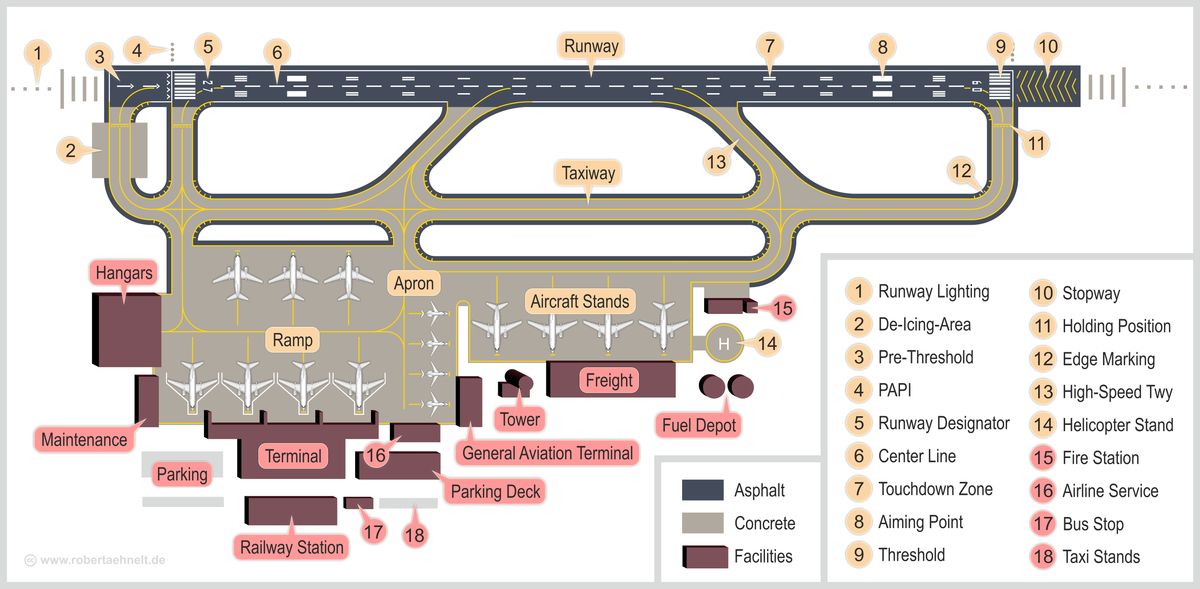
2 Existing Non-Standard Conditions shown in SHADED BOLD TYPE. Introduction To Runways According to the International Civil Aviation Organization ICAO a runway is a defined rectangular area on a land aerodrome prepared for the landing and takeoff of aircraft. Taxiway A taxiway is a path for aircraft at an airport connecting runways with aprons hangars terminals and other facilities.
Geometric Design Standards Length of taxiway Width of taxiway Width of safety area Longitudinal gradient Transverse gradient Rate of change of longitudinal gradient Sight distance Turning radius. Entrance taxiway OUTER COMMON CURVE BYPASS TAXIWAY ENTRANCE TAXIWAY NO TAXIWAY ISLAND C RUNWAY C TAXIWAY L L Figure 4-6. The elevated concrete LOD texture sometimes glitches.
AIRPORT DESIGN STANDARDS AND RUNWAY LENGTH CHAPTER 3 PullmanMoscow Regional Airport Master Plan Phase 1 3-3 NOTES. FAA Advisory Circular 1505300-13 Change 9 Airport Design September 2005. If anyone has any ideas why please let me know.
Orientation Wind Rose Diagram Problems on basic and Actual Length Geometric Design Elements of Taxiway Design Airport Zones Passenger Facilities and Services Runway and Taxiway Markings. Direction Sign for Runway Exit While on the runway this sign will indicate the approaching taxiway. Runway Sign Taxiway Guidance Sign Stand Information Sign 3.
Limit the number of runway crossings. CE8702 RADHE Unit 1 notes Download Here. Optimize taxiway flows to limit the amount of runway crossings.
Full PDF Package Download Full PDF Package. Runway Lights Runway End Identifier Lights REILs. DESIGN ELEMENTS OF TAXIWAY.
A short summary of this paper. I believe this is a problem with the game and not one I can fix. 3 Existing airfield design standards applicable to Pullman-Moscow Regional Airport.
Runways Runway Shoulders and Blast Pads Runway Safety Areas Runway Object Free Areas RUNWAY DESIGN. Revised April 2007 Chapter 13 Runway And Taxiway Marking markings become parallel. More from my site.
For taxiways crossing a runway the taxiway centerline marking may continue across the runway but must be interrupted for the runway markings. The FAA Office of. A pair of white flashing lights one on each side of the approach end of the runway that help identify the runway from taxiways at night.
Orientation Wind Rose Diagram Runway length Problems on basic and Actual Length Geometric design of runways Configuration and Pavement Design Principles Elements of Taxiway Design Airport Zones Passenger Facilities and Services Runway and Taxiway Markings and lighting. 44 Chap 4 OUTER COMMON CURVE C RUNWAY C TAXIWAY L L Figure 4-5. REDIM is a computer model developed to locate and design high-speed runway and right angle exits at airports.
Asok DACHARLA mtech 1 st year Gmr institute of technology Taxiway Taxiways are defines as paths on the airfield surface for the taxing of aircraft and are intended to provide linkage between one part of the airfield and another. UNIT IV AIRPORT DESIGN CE6604 notes. Doc 9157 - Aerodome design manual part 2 taxiway up date.
The code references For detailed design of runway and taxiway intersections or have been specified at various related places to facilitate intersections between two taxiways the local ground profile better understanding of the design procedure. Anna University CIVIL RADHE. Aircraft movement on taxiways are essentially ground movements and are relatively slow compared.
It is located at the far end of the intersection. Note 2 Guidance on determining the runway length is given in the Aerodrome Design Manual Doc 9157 Part 1 Runways. Runways may be a man-made surface often asphalt concrete or a mixture of both or a natural surface grass dirt gravel ice or.
This marking is also placed at taxiway entrances that are closed. 21414 2 AC 1505300-13 CHG 17 9302011. 1 Regulatory Requirements and Definition of Terms.
EB-75 AC 1503500-13A Ch1. They are used when the.

Taxiway And Exit Taxiway Design Notes For Gate Civil Engineering Exams
2
2
Airport Wikipedia

Pdf Airport Layout Plan For Efficient Airport Design

Chapter 4 Apron Planning And Design Apron Planning And Design Guidebook The National Academies Press
Taxiway And Exit Taxiway Design Notes For Gate Civil Engineering Exams
Pdf Airport Layout Plan For Efficient Airport Design
0 comments
Post a Comment